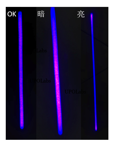
When searching for "line laser" on search engines, various manufacturers and images abound, making the options seem overwhelmingly rich. Yet, many technical personnel in machine vision equipment manufacturing often find themselves deeply frustrated and troubled. Why? Take a look at the figure below:

People can see that all the lines appear "straight," so why the frustration? Consider these points:
First Type of Frustration: The Uniformity Metric Mystery
As seen in the figure above, you might notice:
1. Brighter ends or a brighter middle, with uneven thickness and brightness.
2. Broken lines at the ends, while the middle looks fine.
3. Excessive background stray light.
Second Type of Frustration: Easy to Fail or Dim Over Time
1. During installation and debugging, it works fine today but fails the next day.
2. Deployed at a customer site, it fails after a few days.
3. Gradually dims over time.
Third Type of Frustration: Red, Green, Blue, and Purple Lasers—Prices Range from Tens to Tens of Thousands of RMB, How to Choose?
1. Why do others say blue light is better—should I use it?
2. Why does one unit cost 8,000–10,000 RMB, while another costs only 300 RMB?
Below, we share our R&D experience in industrial machine vision lasers, hoping to contribute these insights as valuable knowledge!
[Basics] How Is a Line Laser Generated?
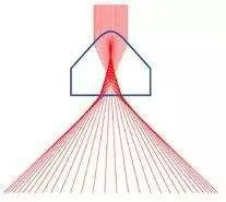
Devices that generate line lasers include cylindrical lenses/wavy lenses, Powell lenses, and DOE (Diffractive Optical Elements). These three methods are common, with materials ranging from plastic to glass. The first two methods fall under geometric optics, while DOE belongs to diffractive optics—each has its pros and cons. We focus on Powell lens-based line lasers here. Products generated by other methods are not recommended, or even opposed, for industrial machine vision applications, especially in 3D measurement. Using them will inevitably lead to frustration; the underlying theory dictates they are "bronze-level" solutions. If you treat them as "champions," frustration is guaranteed. Referencing the widely circulated schematic of Powell lens beam-forming principles (not shown), note the curved ridge of the Powell lens—its machining quality determines the laser line's performance. If you’re familiar with Zemax, simulating the distribution function of this ridge curve and comparing it with cylindrical lenses will clarify the differences. If not, remember: among the three methods, the Powell lens is the champion. Choosing it is the first step to avoiding frustration.

[Solving the First Type of Frustration]
The core of the first frustration lies in the quality mismatch of the line-generating device. For example, cylindrical lenses naturally cause edges to gradually darken. Wavy lenses, essentially multiple connected cylindrical lenses, mitigate edge darkening but still suffer from unevenness. Thus, lines generated this way rarely achieve over 85% uniformity, often featuring broken ends. However, these products suffice for applications like straight-line guidance or marking, where high volumes and low prices make them popular and common. DOE-type line lasers are thin, super compact, and cheap, but they tend to produce a central zero-order spot, leading to discrete breakpoints on dark objects. These are suitable as indicator lights for human vision, not as information sources in machine vision 3D measurement. Powell lens-generated line lasers are the ideal choice for high-end industrial needs, but even they can exhibit brightness issues at the ends. A well-machined Powell lens, designed to specifications, can reshape Gaussian beams into uniform lines with over 95% uniformity—reaching up to 99% in optimal cases. The root cause is mismatched parameters: if the Powell lens is designed for an incident beam diameter of D=3mm but the actual beam is R=3.2mm, the ends darken; if R=2.8mm, the ends brighten. Larger deviations worsen the unevenness. For instance, a mere 0.1mm difference between D and R produces noticeable non-uniformity during debugging.

Understanding this, ask manufacturers: "How do you ensure the incident beam diameter matches the Powell lens?" Professional questions lead to professional answers—this is key to avoiding frustration. For manufacturers, improving this matching is a core competitive advantage.
[Solving the Second Type of Frustration]
This is highly frustrating but simple in cause: excessive current exceeding thresholds leads to Laser Diode (LD) burnout, or LDs operating long-term at the maximum limit specified in datasheets! Numerous drive circuit schematics exist online—they work, but the devil is in the details. Issues include: flawed circuit design, lack of ESD protection, or improper capacitor components. LDs are static-sensitive devices—fragile and prone to damage. Analysis of many constant-current source designs reveals problems like overshoot currents from PWM signal adjustments, peak current spikes at power-on, and external ground current leaks. Some drive boards work stably with Manufacturer A’s LDs but fail with Manufacturer B’s. These flaws may stay hidden if the product is sealed as a finished unit without external control cards. However, in machine vision, where external control cards sync with cameras, these limitations surface. How to solve and avoid this? Implement ESD protection measures: ensure a well-grounded installation environment, have personnel wear anti-static wristbands, and add electrostatic discharge devices to prevent issues during setup. Equally crucial is selecting robust designs with industrial-grade components—any subpar part can compromise quality. Testing-wise, laser modules must pass ESD 4KV and voltage surge tests—this demands co-optimization of design and assembly by the manufacturer. Without design capability, root solutions are impossible. If you encounter this frustration, switch to a professional industrial machine vision laser manufacturer immediately. Manufacturers must rigorously review designs, test for hidden flaws, and identify defects through intensive validation, covering circuits and structures. User scenarios vary wildly, so the only solution is accumulating experience and iterating rapidly to improve quality.
[Solving the Third Type of Frustration]
This stems purely from inexperience—hopefully resolved by reading this guide. Wavelength selection depends on the application: red light performs well on non-metallic surfaces like plastic, and many cameras have strong red-band response, making red common in machine vision projects. Blue light excels on metallic surfaces. Green light sits between red and blue, with peak human eye sensitivity—minimal power appears intensely bright. Choose green for human-visible emphasis, but for invisibility, opt for 800–940nm IR lasers. Thus, the core factors are application context and camera configuration, dictating the optimal wavelength.
As for price frustration, it’s subjective. A 10,000 RMB laser is market-accepted for reasons like ultra-fine line widths (10–100μm), high consistency (deviations under 5% across thousands of units), uniformity >95%, straightness ≤0.1%, plus brand premium—it’s about buying peace of mind and leveraging others’ expertise to boost your product’s competitiveness. Without brand bias, lasers costing over 1,000 RMB far outperform cheaper ones in specs. Discussing price without performance metrics is the root of frustration. The solution: revisit the first and second frustrations, master the causes and principles, then select a suitable product with a realistic budget based on specs—naturally ending price woes.